Facts About Wedge Barriers Revealed
Some Known Questions About Wedge Barriers.
Table of Contents9 Easy Facts About Wedge Barriers DescribedThe smart Trick of Wedge Barriers That Nobody is Talking About
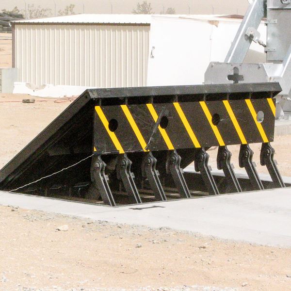
14 and the surface area 12 to which the obstacle 10 is secured might be made from concrete - Wedge Barriers. 2, the obstacle 10 is installed to or consists of a support or subframe (e. g., anchor 30 shown in FIG. 2 )safeguarded under the surface 12. The bather 10 might be bolted to the support or protected to the support by various other mechanical bolts. In the illustrated personification, the barrier 10 consists of a wedge plate 16, which consists of a portion that is significantly identical with the surface 12 when the obstacle 10 is in the retracted placement. In various other words, automobiles or people might pass over the obstacle 10 when the obstacle 10 remains in the pulled back setting and experience minor elevation about the surface 12 while on the obstacle 10. As discussed thoroughly below, when the obstacle 10 remains in the deployed position, the wedge plate 16 is held and supported in an increased position by a training mechanism of the barrier 10. Additionally, the parts 18 might be bolted or otherwise mechanically combined to one an additional. In this manner, repair service or substitute of one or even more parts 18 might be streamlined and streamlined. That is, repair service or substitute of solitary elements
18 might be done anonymous faster, quickly, and cost successfully. FIG. In specific embodiments, the support 30 may be a steel structure consisting of plates, beam of lights(e. g., I-beams ), and/or other structures that are secured within the structure 14, which might be concrete. At the surface area 12, a top side 28 of the support 30 might be at the very least partially subjected
, thus making it possible for the add-on of the obstacle 10 to the support 30. g., threaded holes)in one or more light beams or plates of the anchor 30 might be exposed to the surface area 12. In this fashion, screws 32 or other mechanical bolts might be utilized to safeguard the barrier 10 to the support 30. As the barrier 10 is mounted to the surface area 12 of the structure 14, collection of debris and various other product under the obstacle might be minimized, and components of the bather 10 might not be revealed to listed below quality environments. As indicated by referral numeral 52, the lifting device 50 consists of elements disposed beneath the wedge plate 16. The components 52 underneath the wedge plate 16 may include an electromechanical actuator, a camera, one or more web cam surface areas, and so forth. Additionally, the training device 50 includes a spring assembly 54
The springtime pole 58 is paired to a webcam(e. g., camera 80 revealed in FIG. 4) of the training mechanism 50. The springs 60 disposed about the spring pole 58 are held in compression by springtime supports 62, including a repaired spring support 64. That is, the fixed springtime assistance 64 is taken care of about the structure 14 and the remainder of the bather 10.
Some Known Factual Statements About Wedge Barriers
g., spring support 65 )may be dealt with to the end of the spring rod 58 to make it possible for compression of the springs i thought about this 60. As the springs 60 are compressed between the spring supports 62, the spring assembly 54 produces a pressure acting on the web cam paired to the springtime rod 58 in a direction 66. The continuing to be pressure applied to
the cam to deploy release wedge plate 16 may might provided offered an electromechanical actuator 84 or other various other. The springtime setting up 54 and the actuator 84(e. g., electromechanical actuator)might run with each other to convert the cam and lift the wedge plate 16.
As stated over, in the deployed placement, the wedge plate 16 offers to block access or travel past the obstacle 10. The barrier 10(e. g., the wedge plate 16 )may block pedestrians or automobiles from accessing a residential property or path. If a lorry is traveling in the direction of the released wedge plate 16(e. For instance, in one scenario, the his explanation security legs 86 may be extended duringmaintenance of the barrier 10.